
How Big Stainless Sculptures Stay Standing: Wind Load, Weight & Base Explained
September 16, 2026
The question almost every client asks when commissioning a large stainless steel sculpture is wind load: will a six-metre piece really stay standing in a storm? The reassuring answer is yes — routinely, and to a defined standard. Wind loading on outdoor sculpture is a solved engineering problem, calculated to codes such as ASCE 7 in the United States and EN 1991-1-4 in Europe, and the numbers are usually smaller than clients expect. What matters is that the calculation happens before fabrication, and that the base is designed alongside the artwork instead of being improvised on site.
Why scale changes the engineering of a large stainless steel sculpture
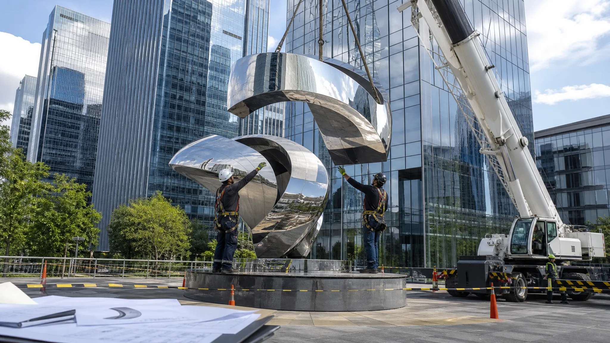
A sculpture under about two metres is essentially self-supporting. Its own mass does the structural work, wind is a nuisance rather than a design driver, and a simple bolted plate is usually enough. Past roughly four to five metres, that stops being true. Wind load on a large stainless steel sculpture grows far faster than height, for three compounding reasons:
- Sail area — the silhouette presented to the wind grows with the square of the height. Double the height and you roughly quadruple the exposed area.
- Wind pressure itself — wind speed increases with height above ground, so the pressure acting on the upper part of a tall piece is higher than at ground level.
- Moment arm — the force acts higher up, so the bending moment at the base is the force multiplied by a taller lever arm.
Multiply those together and the overturning moment at the base scales roughly with the cube of height. A six-metre version of a two-metre form can carry twenty times the bending load at its foundation. That does not make it unsafe — it makes it a structure. Real load paths, real connections, and a real foundation, all of which are ordinary engineering when they are designed in from the start.
What wind load actually is on a large stainless steel sculpture
Structural engineers reduce wind to four inputs. Once you have them, the force on any sculpture — however abstract — can be estimated with reasonable accuracy.
Dynamic pressure. Wind pressure rises with the square of wind speed. In metric terms q = 0.613 V², where V is wind speed in metres per second and q is in newtons per square metre. ASCE 7 expresses the same relationship as qz = 0.00256 Kz Kzt Kd V² with V in mph and qz in pounds per square foot. V is not a guess: it comes from the code’s basic wind speed map for the site, then adjusted for height (Kz), local topography such as a hilltop or escarpment (Kzt), and wind directionality (Kd).
Exposure category. A sculpture in a dense city centre is sheltered by buildings and trees; one on an exposed seafront or an open plain is not. ASCE 7 describes this with Exposure B (urban/suburban), C (open terrain) and D (flat, unobstructed water or mudflats); Eurocode uses terrain categories 0 to IV. Two identical pieces in two cities will legitimately receive different foundations because of this one input.
Sail area. This is the projected frontal area — the sculpture’s silhouette, perpendicular to the wind. A thin, wide ribbon can present a far larger sail than a compact form of the same height and weight.
Shape factor. The drag coefficient Cf (or cd) accounts for how the wind separates around the form: roughly 0.5 for a smooth sphere, about 1.2 for a cylinder, up to 2.0 for a flat plate, and typically 1.2–1.5 for the curved, semi-open shapes of abstract stainless work. A conservative analysis uses the higher end. A gust effect factor of about 0.85 applies to the rigid, low-frequency structures that most sculptures are.
Real numbers: a worked example to ASCE 7 and EN 1991-1-4
Take a six-metre-tall abstract stainless sculpture, 1.5 m wide, on a commercial plaza in a US city with a basic wind speed of 90 mph (about 40 m/s), Exposure B. The silhouette presents a sail area of about 9 m².
| Step | Input | Value |
|---|---|---|
| Velocity pressure (ASCE 7) | Kz 0.9, Kzt 1.0, Kd 0.85, V 90 mph | ≈ 0.76 kN/m² |
| Cross-check (EN 1991-1-4) | vb 26 m/s, terrain cat. III, z = 6 m | ≈ 0.63 kN/m² |
| Drag coefficient | Cf = 1.3, gust factor 0.85 | — |
| Design force | F = q × G × Cf × A | ≈ 7.5 kN |
| Overturning moment | Force × 3.5 m centre of pressure | ≈ 26 kN·m |
| Stabilising moment | 1.5 safety factor | ≈ 39 kN·m |
So a six-metre stainless landmark is designed for roughly 7.5 kilonewtons of horizontal push — about three-quarters of a tonne, the weight of a compact car leaning steadily against the base. Both codes land within a few percent of each other once their different averaging periods are reconciled, which is exactly what you want to see: the answer is not sensitive to which standard the engineer picks.
Weight and stability: overturning moment versus base mass
Stainless fabrication is thin-walled, so a six-metre hollow piece often weighs only 300 to 600 kg. That creates the central paradox of sculpture engineering: the lighter and more graceful the artwork looks, the harder the base has to work. The sculpture resists wind not by being heavy but by being firmly tied to something that is.
The governing check is overturning. The wind tries to rotate the piece about the downwind edge of its base. That must be resisted either by the mass of the foundation, or by tension in the upwind anchor bolts, or — usually — a combination of both. From the worked example, the required restoring moment is about 39 kN·m, and a reinforced concrete pad of roughly 1.6 m × 1.6 m × 1.0 m — around six tonnes — supplies about 48 kN·m, comfortably above it. On an existing slab where no such pad can be cast, the anchor bolts are instead designed to take the uplift tension, which is why the slab’s thickness and reinforcement have to be verified before the anchors are specified.
Public artwork above a certain height frequently requires a stamped structural design from a locally licensed engineer. We supply the design force, the reactions and the connection geometry; the foundation is typically detailed by an engineer local to your site, who signs off on local soils and codes. That division of responsibility is normal and keeps your approval process clean.
Base and anchorage options: bolted, grouted, ballast
The base is where the artwork stops being art and becomes infrastructure. There are three standard approaches, and the choice is usually driven by the finish and the site rather than by structural capacity.
Bolted base plate. A laser-cut stainless plate welded to the internal armature, fixed down with M20–M30 anchor bolts into cast-in-place concrete or chemical anchors into an existing slab. It is the most explicit option: inspectable, adjustable during installation, and removable — the sculpture can be unbolted and craned away for cleaning or relocation. The trade-off is a visible bolt ring, which many clients hide under a decorative stainless skirt.
Grouted socket. The sculpture’s base sleeve is set into a formed pocket in the foundation and filled with non-shrink structural grout. The result is extremely rigid with no visible fixings, which is why it is the default for mirror-polished work on plazas and in water features. It is effectively permanent — dismantling means breaking out the socket.
Ballast base. Where the surface cannot be penetrated — roof terraces, podium decks, leased retail forecourts, indoor atria — the piece is carried on a weighted steel or concrete plinth sized so its own mass provides the restoring moment. The structure below must still be checked for the added dead load.
In every case the sculpture needs an internal armature: a stainless tube or plate spine sized for the bending moment, with the skin welded to it.
Why fabrication tolerance matters: seams and wall thickness
Wind engineering sets the loads; fabrication quality decides whether the piece actually achieves them. Three details matter more than any other.
Wall thickness. Three millimetres is common for sculptural skins, but four to six millimetres is typical where panels are large or the piece stands free above four or five metres, so the skin cannot buckle between internal ribs. Thicker is not automatically better: unnecessary weight loads the foundation, and heavier sections weld with more distortion. The right thickness is a design decision, not a default.
Seam quality. Critical seams are butt-welded and back-purged for full penetration, then ground and polished flush. A cold lap, undercut or incomplete fusion is not merely cosmetic — it is a stress riser and a corrosion site. On 316 stainless in coastal air, a crevice is where tea-staining begins, and on a cyclically loaded sculpture it is also where a fatigue crack would start. Critical welds are inspected, and the alloy itself is sometimes verified by positive material identification to confirm that 316 is genuinely 316.
Dimensional tolerance. Mirror-polished panels reveal every misalignment. Acceptable step between adjacent panels is measured in fractions of a millimetre, and each weld shrinks as it cools, so weld sequence and tacking plans control distortion rather than repair it afterwards. Tolerances must be agreed before cutting.
What this means for your commission
None of this is exotic, and none of it should be a surprise revealed after deposit. A properly run project freezes the wind load calculation and the base concept before any stainless is cut, then delivers a piece whose reactions your local engineer can design to.
See how we run that sequence end to end on our fabrication process page, browse completed works for scale and context, or look at the abstract stainless landmark we fabricated for a commercial plaza — a piece of exactly this height and type. If you have a site and a sketch, send us both, and we will come back with the design force, the base concept and a realistic programme.
More from the Workshop
Have a Project in Mind?
Send your brief and get a free, honest quote within 24 hours — no obligation.
Request a Quote